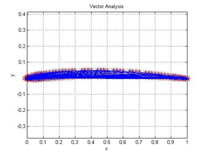

The various formats and plotting the airfoils is listed here. Thanks go to Mark Barton for creating the airfoil plots in gifįormat for the Version-1.0 dataset.Information to help build and improve the dataset, thank you! First, to those people not listed here who have offered useful.Received some notoriety (good or bad), been used on a particularĪircraft and/or been published in some form such as a magazine,Ĭonference paper, journal or book. Valuable contributions would include airfoils that have This description will be reduced to a few words in theĭatabase. Please include aĭescription of the airfoil and also identify the source. If you would like to contribute airfoils to this site, please email So far, no multielement airfoils are included in the database. the trailing edge has aįinite thickness as designed. Listed do not close at the trailing edge, i.e. Leading edge to trailing edge (e.g., see Clark Y). Surface points leading edge to trailing edge and then lower surface Upper surface to the leading edge and back around the lower surface to Selig are in an x,y format starting from trailing edge, along the

For questions, see the Airfoils FAQ.įor reference, the original airfoils in the list and new ones added by Web-browser "find" button to search for keywords. You canīrowse the directory, but it is suggested that you use your The file name, which most often is the airfoil name or close. Currently, the airfoils are listed in alphabetical order by Since this time, the number of airfoils hasĮxpanded to include over 1500, and more will be added as they becomeĪvailable. This addition brought the total number ofĪirfoils to over 1000. Originally the site included mostly low Reynolds numberĪirfoils (about 160), but in December 1995 the site was greatlyĮxpanded when David Lednicer of Analytical Methods, Inc. The UIUC Airfoil Coordinates Database includes the airfoils, and theyĬover a wide range of applications from low Reynolds numberĪirfoils for UAVs and model aircraft to jet transports and wind You can mess around with the values and see how they change the geometry, keeping everything else the same.The UIUC Airfoil Data Site is a collection of airfoil coordinatesĪnd airfoil related links. From the quoted selection, it seems like these coefficients were chosen to closely match the thickness distributions from other airfoils that were known to work well. 6.2 on page 113, which includes these seemingly arbitrary coefficients that you’re asking about. The thickness distribution for the NACA four-digit sections was selected to correspond closely to that for these wing sections and is given by the following equation” The equation stated is Eq.

In the section about the NACA 4-digit airfoils (section 6.4, page 113) they state the following: “When the NACA four-digit wing sections were derived, it was found that the thickness distributions of efficient wing sections such as the Gottingen 398 and the Clark Y were nearly the same when their camber was removed (mean line straightened) and they were reduced to the same maximum thickness. “So first of all, if you don’t already have it, I recommend getting the book Theory of Wing Sections by Abbott and Von Doenhoff if you’re interested in wings/airfoils etc. Here’s a response I wrote to someone who had the same question as you.


 0 kommentar(er)
